Stroke is the distance the piston travels between its two extreme positions — top dead center (TDC) and bottom dead center (BDC). Unlike bore, which can change through wear or machining, stroke is a fixed geometric property of the crankshaft. It equals exactly twice the offset (throw) between the crankshaft’s main bearing journal and its rod bearing journal.
Measuring stroke accurately matters because it feeds directly into displacement, piston speed, and rod ratio calculations. A 1 mm stroke error on a V8 produces a 65 cc displacement error — enough to misclassify an engine in competition or mis-specify parts during a build.
What Determines Stroke
Stroke is set by the crankshaft, not by the block, pistons, or connecting rods. Specifically:
Stroke = 2 × Crank Throw
The crank throw is the distance between the centerline of the main bearing journal (which the crank rotates around) and the centerline of the rod bearing journal (where the connecting rod attaches).
| Crankshaft Dimension | Description | Typical Range |
|---|---|---|
| Main journal | Center of rotation | Fixed in block |
| Rod journal | Connecting rod attachment | Offset from main |
| Crank throw | Offset distance | 38–55 mm (common V8) |
| Stroke | 2 × throw | 76–110 mm (common V8) |
A stock Chevy 350 crankshaft has a throw of 44.2 mm, producing a stroke of 88.4 mm (3.480”). A 383 stroker crankshaft has a throw of 47.65 mm, producing a stroke of 95.3 mm (3.750”).
3 Methods to Measure Stroke
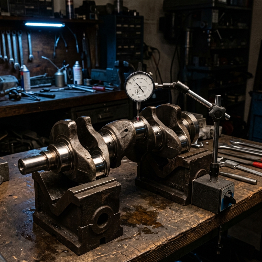
Method 1: Direct Crankshaft Measurement (Most Accurate)
Tools needed: V-blocks, dial indicator with magnetic base, and a flat surface plate.
Procedure:
- Place the crankshaft on V-blocks, supporting it by the front and rear main journals.
- Mount a dial indicator so the plunger contacts the top of one rod journal.
- Rotate the crankshaft slowly through 360°.
- Record the maximum and minimum indicator readings.
- Stroke = Maximum reading − Minimum reading
This method measures stroke directly from the crankshaft geometry, independent of the block, pistons, or connecting rods. It is the reference standard.
Accuracy: ±0.001” (0.025 mm) with proper technique.
Method 2: In-Block Measurement with Dial Indicator
Tools needed: Dial indicator with extension, degree wheel (optional).
Procedure:
- Install the crankshaft and one connecting rod with piston in the block (no head).
- Mount a dial indicator on the deck surface with the plunger contacting the piston crown.
- Rotate the crankshaft to find TDC — the point where the indicator reading is at maximum.
- Continue rotating to find BDC — the point where the indicator reading is at minimum.
- Stroke = TDC reading − BDC reading
This method includes the actual rod and piston assembly, which can reveal practical geometry issues that direct crank measurement does not.
Accuracy: ±0.002” (0.05 mm) — slightly less accurate because piston rock at dead centers can affect the reading.
Method 3: Spec Sheet Lookup (Fastest, Least Accurate)
Procedure: Look up the crankshaft part number in the manufacturer’s specifications or the aftermarket catalog.
| Source | Reliability |
|---|---|
| OEM service manual | High — verified engineering data |
| Aftermarket crank catalog (Scat, Eagle, Callies) | High — machined to specification |
| Online forums | Low — often rounded or incorrect |
| Badge on the engine | Unreliable — marketing, not measurement |
Accuracy: Depends entirely on the source. OEM specs are typically accurate to ±0.1 mm.
Finding True Top Dead Center
The most critical part of stroke measurement is accurately locating TDC. Near the top of the stroke, the piston barely moves despite significant crankshaft rotation — this is the dwell zone where the rod angle makes piston position insensitive to crank angle.
The Positive-Stop Method
The most accurate way to find TDC uses a positive stop (a fixed barrier in the spark plug hole or on the deck surface):
- Install a positive stop that prevents the piston from reaching full TDC.
- Rotate the crank clockwise until the piston contacts the stop. Record the degree wheel position (e.g., 22° BTDC).
- Rotate the crank counterclockwise until the piston contacts the stop from the other side. Record the position (e.g., 22° ATDC).
- True TDC is exactly halfway between the two readings.
This method eliminates the uncertainty of trying to find TDC by watching a dial indicator hover at its maximum reading.
Why the Dwell Zone Causes Errors
Near TDC, the piston position changes by less than 0.001” per degree of crankshaft rotation. Without a positive stop, it is easy to be 2–3° off true TDC — which does not significantly affect the stroke reading but causes major timing errors if the degree wheel is being used to set cam timing or ignition advance.
How Stroke Measurement Errors Cascade
A stroke measurement error affects every calculation that uses stroke as an input:
| Calculation | Impact of +1 mm Stroke Error (V8) |
|---|---|
| Displacement | +65 cc (+4.0 CID) |
| Mean piston speed (at 6,000 RPM) | +0.2 m/s |
| Rod ratio (with 154.9 mm rod) | Changes from 1.752 to 1.739 |
| Compression height estimate | −0.5 mm (shorter than actual) |
| Required stroke in stroker planner | Off by 1 mm target |
The displacement error alone is significant — 65 cc is the difference between a “5.7L” and a “5.8L” classification. For competition engines with class displacement limits, this error can mean disqualification.
Stroke and Its Downstream Effects
Mean Piston Speed
Stroke directly determines how fast the piston moves at any given RPM:
Mean Piston Speed = 2 × Stroke × RPM ÷ 60
| Stroke | Speed at 5,000 RPM | Speed at 6,500 RPM | Speed at 8,000 RPM |
|---|---|---|---|
| 76.2 mm (3.000”) | 12.7 m/s | 16.5 m/s | 20.3 m/s |
| 88.4 mm (3.480”) | 14.7 m/s | 19.1 m/s | 23.6 m/s |
| 95.3 mm (3.750”) | 15.9 m/s | 20.6 m/s | 25.4 m/s |
| 101.6 mm (4.000”) | 16.9 m/s | 22.0 m/s | 27.1 m/s |
The widely accepted limit for cast pistons is 20 m/s and for forged pistons is 25 m/s. A stock 350 (88.4 mm stroke) at 6,500 RPM reaches 19.1 m/s — safely within cast-piston limits. A 383 stroker (95.3 mm) at the same RPM reaches 20.6 m/s — requiring forged pistons.
Use the mean piston speed calculator to check your combination against material limits.
Rod-to-Stroke Ratio
The rod ratio determines connecting rod angularity and piston side-loading:
Rod Ratio = Rod Length ÷ Stroke
A longer stroke with the same rod produces a lower ratio, more rod angle, and more piston side-loading. This is why stroker engines often benefit from longer connecting rods to maintain a favorable ratio.
Check your combination with the rod-to-stroke ratio calculator.
Compression Height
In a stroker build, the block deck height is fixed. As stroke increases, the piston compression height (wrist pin to crown) must decrease to prevent the piston from protruding above the deck. An inaccurate stroke measurement leads to ordering pistons with the wrong compression height — a potentially expensive mistake.
Model the full geometry with the stroker engine planner.
Stroke vs. Bore: Which Matters More for Displacement?
Bore is squared in the formula. Stroke is linear. This means:
| 1% Change In | Displacement Change |
|---|---|
| Bore | ≈ 2% (quadratic) |
| Stroke | ≈ 1% (linear) |
However, stroke changes are mechanically simpler for large displacement gains — a 0.250” stroke increase adds 25+ CID while a 0.030” overbore adds only 5 CID. The stroke route produces larger gains per modification, even though each millimeter of stroke is worth slightly less than each millimeter of bore on a per-unit basis.
The Measurement Workflow
- Determine the measurement method based on available tools and engine state.
- Measure stroke to at least 0.01 mm (0.001”) precision.
- Enter the stroke into the engine displacement calculator along with bore and cylinder count.
- Check piston speed at your target RPM using the piston speed calculator.
- Verify rod ratio using the rod ratio calculator.
One measurement — three calculations. That is why getting stroke right is worth the time.