If the bore number you enter into the displacement formula is wrong, every calculation built on it will be wrong too. A 0.002” bore measurement error on a V8 changes displacement by 3.5 CID and piston-to-wall clearance by 0.001” — enough to affect ring seal, oil consumption, and compression ratio.
Accurate bore measurement is not optional for serious engine work. It is the foundation that everything else depends on.
This guide covers the tools, technique, measurement locations, and interpretation needed to get bore diameter right.
The Right Tools for Bore Measurement
Dial Bore Gauge (Primary Tool)
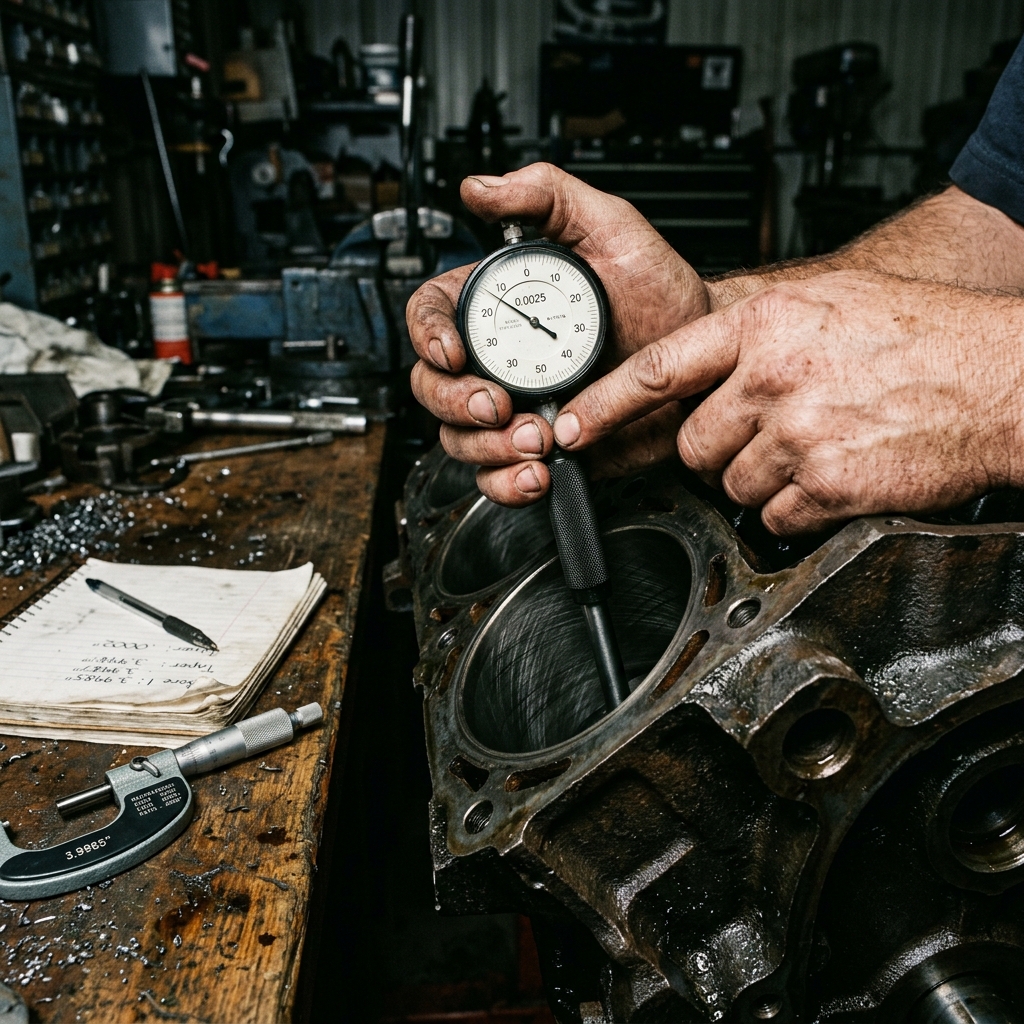
A dial bore gauge is an inside measuring instrument that reads cylinder diameter to 0.0001” (one ten-thousandth of an inch, or 0.0025 mm) resolution. It consists of a contact anvil, a sensitive spring-loaded plunger, and a dial indicator that displays deviation from a reference dimension.
How it works: The gauge is set to a known reference using a micrometer. The gauge is then inserted into the bore and rocked gently until the indicator shows the minimum reading (the true diameter point). The dial shows how much the bore differs from the micrometer setting — plus or minus.
| Specification | Typical Value |
|---|---|
| Resolution | 0.0001” (0.0025 mm) |
| Accuracy | ±0.0002” (±0.005 mm) |
| Range per head | 0.150” (adjustable with extensions) |
| Cost | $150–$400 for quality sets |
Reference Micrometer
The dial bore gauge must be zeroed against a reference. A 1” outside micrometer set (covering 3–5” in 1” increments) provides the baseline dimension. Set the micrometer to the nominal bore size, lock it, then zero the gauge against it.
Alternative Tools
| Tool | Resolution | Best For |
|---|---|---|
| Telescoping gauge + micrometer | 0.0005” | Field verification, budget builds |
| Snap gauge | 0.0005” | Quick go/no-go checks |
| Digital caliper | 0.001” | Rough estimates only — NOT for bore work |
Digital calipers lack the resolution and contact geometry needed for accurate bore measurement. A caliper jaw pressed against a curved surface contacts on a tangent line, not a diameter, introducing systematic error.
Where to Measure: The 6-Point Protocol
Each cylinder should be measured at 6 locations — 3 depths at 2 angles. This protocol reveals both taper (wear along the cylinder length) and out-of-round (distortion across the bore):
The 3 Depths
| Location | Distance from Deck | What It Reveals |
|---|---|---|
| Top (Position A) | 0.5” below deck surface | Ring reversal point — maximum wear zone |
| Middle (Position B) | Center of bore | General bore condition |
| Bottom (Position C) | 0.5” above bottom of bore | Minimum wear zone (reference) |
The 2 Angles
| Angle | Direction | What It Reveals |
|---|---|---|
| Thrust | Perpendicular to crankshaft centerline | Maximum side-loading wear |
| Non-thrust | Parallel to crankshaft centerline | Minimum side-loading wear |
The thrust direction receives the highest piston side-loading during the power stroke. This is where the bore wears fastest and where out-of-round develops first.
Recording the Data
A professional bore measurement sheet records all 6 readings per cylinder:
| Cylinder | Top-Thrust | Top-NonThrust | Mid-Thrust | Mid-NonThrust | Bot-Thrust | Bot-NonThrust |
|---|---|---|---|---|---|---|
| #1 | 4.0012 | 4.0010 | 4.0008 | 4.0007 | 4.0004 | 4.0004 |
| #2 | 4.0015 | 4.0012 | 4.0010 | 4.0009 | 4.0005 | 4.0005 |
| … | … | … | … | … | … | … |
From this data:
- Taper = Top reading − Bottom reading (per angle)
- Out-of-round = Thrust reading − Non-thrust reading (per depth)
Step-by-Step Measurement Procedure
Step 1 — Clean the Bore
Remove all oil, carbon, and debris from the cylinder wall. Any contamination on the bore surface adds to the measurement and produces a false oversized reading. Use a clean rag with solvent, not a wire brush (which can scratch the surface and affect the measurement).
Step 2 — Set the Reference
Lock the outside micrometer to the nominal bore dimension (e.g., 4.000” for a Chevy 350). Place the dial bore gauge contact anvils into the micrometer and zero the indicator. This sets the gauge to read deviation from 4.000”.
Step 3 — Insert and Rock
Lower the gauge into the bore at the desired depth. Gently rock the gauge back and forth in a small arc across the bore diameter. The indicator will sweep through a range — the minimum reading during the rock is the true diameter reading. This minimum-finding technique is critical because any off-center position reads larger than the true diameter.
Step 4 — Record at All 6 Positions
Repeat the insertion and rocking procedure at each of the 6 measurement locations (3 depths × 2 angles) per cylinder. Record every reading.
Step 5 — Calculate Taper and Out-of-Round
- If taper exceeds 0.003” in any cylinder, the bore should be rebored.
- If out-of-round exceeds 0.002” in any cylinder, the bore should be rebored.
- If both are within tolerance, the bore may accept new rings with a light hone.
How Bore Accuracy Affects Calculations
Displacement
The displacement formula uses bore². A 0.002” measurement error on a 4.000” bore changes calculated area by:
(π/4) × 4.002² − (π/4) × 4.000² = 0.00628 sq in per cylinder
Across 8 cylinders with an 88.4 mm stroke: the displacement changes by 1.76 CID (28.8 cc).
Piston-to-Wall Clearance
Piston clearance is typically 0.0015–0.0040” depending on piston material and application. If the bore is measured 0.001” too large, the machinist may cut pistons 0.001” oversized, resulting in actual clearance that is 0.001” tighter than intended — potentially causing piston scuffing during warm-up.
Ring End Gap
Ring end gap is set at 0.004” per inch of bore diameter (typical rule of thumb). A bore measured 0.002” oversized would set the gap 0.001” too wide — not catastrophic, but enough to affect ring seal at the margins.
Common Measurement Mistakes
1. Not Rocking the Gauge
If the gauge is simply inserted and read without rocking, the reading will be off-diameter (too large). The rocking technique finds the true diameter — the minimum reading during the arc.
2. Using a Warm Block
Thermal expansion of cast iron is approximately 0.0006” per inch per 100°F. A 4.000” bore at 150°F (shop temperature after machining) reads 4.0004” larger than at 70°F. Always measure at room temperature, or apply a correction factor.
3. Measuring Through the Ridge
The unworn area at the very top of the bore (above the top ring travel) is the original factory dimension. This ridge is NOT the current bore diameter — it is the pre-wear reference. Measure below the ridge to capture actual worn dimensions.
4. Zeroing to the Wrong Reference
If the micrometer reference is set to 4.000” but is actually 3.9998” due to anvil wear, every bore gauge reading will inherit that 0.0002” systematic error across all 8 cylinders. Verify the micrometer against gauge blocks annually.
When Factory Specs Are Sufficient
Not every situation requires physical measurement:
| Scenario | Use Factory Spec? | Why |
|---|---|---|
| Quick displacement estimate | ✅ Yes | Badge-level accuracy is fine |
| New crate engine with zero miles | ✅ Yes | Bore is at factory spec |
| Used engine, unknown history | ❌ No | Wear and prior machining unknown |
| Post-overbore verification | ❌ No | Must verify actual cut size |
| Competition class compliance | ❌ No | Tech inspectors will measure |
The Measurement-to-Calculator Workflow
- Measure all cylinders using the 6-point protocol.
- Use the largest reading (typically the top-thrust position in a worn engine) as the effective bore for displacement calculation.
- Enter that bore into the engine displacement calculator along with stroke and cylinder count.
- Use the bottom-of-bore reading (minimum wear) as the reference for determining overbore amount needed.
- Feed the planned overbore size into the overbore displacement calculator to see the final result.
The calculator is only as honest as the bore number you give it. Accurate measurement is the first step in every reliable build plan.