Combustion chamber volume is the most sensitive variable in the compression ratio equation. A 5 cc change in chamber size moves the ratio by 0.5 to 0.8 points — more than any other single adjustment short of a piston swap. Cylinder head milling is the most precise way to reduce that volume, and it is one of the most common machine shop operations in performance engine building.
This guide explains what chamber volume is, how milling changes it, how much each thousandth of cutting removes on popular engine families, and when milling is the right approach versus alternative methods.
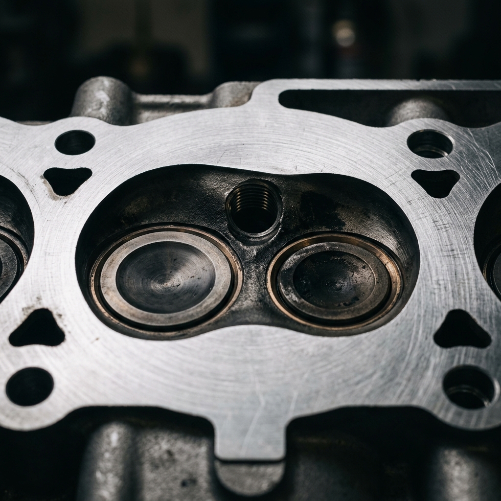
What Is Combustion Chamber Volume?
The combustion chamber is the enclosed space above the piston at top dead center where the air-fuel mixture is compressed and ignited. Its volume — measured in cubic centimeters (cc) — is one of the primary inputs to the compression ratio formula:
CR = (Swept Volume + Clearance Volume) ÷ Clearance Volume
Clearance volume includes:
- Combustion chamber volume (the largest component, typically 55–85% of total clearance)
- Head gasket volume
- Deck clearance volume
- Piston crown volume (dome subtracts, dish adds)
Because chamber volume is the single largest contributor to clearance volume, small changes in chamber size produce proportionally large changes in compression ratio.
How Chamber Volume Varies Across Engine Families
Different cylinder head designs have very different stock chamber volumes:
| Engine Family | Head Type | Stock Chamber (cc) | Typical CR |
|---|---|---|---|
| Chevy SBC (early) | Cast iron, open | 76 cc | 8.0–8.5:1 |
| Chevy SBC (Vortec) | Cast iron, D-shape | 64 cc | 9.0–9.5:1 |
| Chevy LS1/LS6 | Aluminum, cathedral port | 64–68 cc | 10.0–10.5:1 |
| Ford 351W | Cast iron, open | 60–66 cc | 9.0–9.5:1 |
| Ford Coyote 5.0 | Aluminum, 4V | 51–54 cc | 11.0:1 |
| Honda K20A | Aluminum, pentroof | 50 cc | 11.0:1 |
| Chrysler LA 340 | Cast iron, open | 72–78 cc | 8.5–10.5:1 |
| GM LS3/L99 | Aluminum, rectangular port | 68 cc | 10.7:1 |
Notice the trend: newer engines use smaller chambers and higher compression ratios. Modern combustion chamber designs are more efficient at resisting detonation, allowing higher CR on pump fuel.
How Cylinder Head Milling Works
Milling removes material from the cylinder head’s deck surface — the flat face that mates against the head gasket. This reduces the depth of the combustion chamber, which reduces chamber volume, which reduces clearance volume, which raises compression ratio.
The CC-Per-Thousandth Relationship
The volume removed per thousandth of milling depends on the chamber shape and bore diameter. For common engine families:
| Engine | Bore (in) | CC Removed per 0.010” | CC per 0.001” |
|---|---|---|---|
| Chevy SBC (4.000” bore) | 4.000 | 2.06 | 0.206 |
| Chevy SBC (4.030” bore) | 4.030 | 2.10 | 0.210 |
| Chevy BBC (4.250” bore) | 4.250 | 2.33 | 0.233 |
| Ford 302/351W (4.000” bore) | 4.000 | 2.06 | 0.206 |
| Ford Coyote (3.630” bore) | 3.630 | 1.70 | 0.170 |
| Honda K20 (86 mm bore) | 3.386 | 1.48 | 0.148 |
| GM LS (3.898” bore) | 3.898 | 1.96 | 0.196 |
The formula for calculating volume removed per cut is:
Volume removed = (π ÷ 4) × Bore² × Cut Depth
This assumes the entire bore area contributes to chamber volume reduction, which is approximately true for most modern chamber designs. Open-chamber heads may deviate slightly because part of the chamber extends beyond the bore diameter.
Milling Amount Reference Table
For a Chevy SBC with 76 cc open chambers and 4.030” bore:
| Mill Amount | Volume Removed | New Chamber (cc) | CR Change (approx.) |
|---|---|---|---|
| 0.010” | 2.10 cc | 73.9 | +0.15 |
| 0.020” | 4.19 cc | 71.8 | +0.30 |
| 0.030” | 6.29 cc | 69.7 | +0.45 |
| 0.040” | 8.39 cc | 67.6 | +0.60 |
| 0.060” | 12.58 cc | 63.4 | +0.90 |
For a Vortec head with 64 cc chambers and the same bore:
| Mill Amount | Volume Removed | New Chamber (cc) | CR Change (approx.) |
|---|---|---|---|
| 0.010” | 2.10 cc | 61.9 | +0.20 |
| 0.020” | 4.19 cc | 59.8 | +0.40 |
| 0.030” | 6.29 cc | 57.7 | +0.55 |
Notice that the same mill amount produces a larger CR change on the smaller-chamber Vortec head. This is because the same absolute cc reduction represents a larger percentage of the smaller total clearance volume.
5 Consequences of Head Milling Beyond Compression
1. Intake Port Entry Angle Changes
Milling the deck surface moves the intake port opening closer to the gasket surface, altering the port entry angle. Excessive milling (beyond 0.040–0.060”) can create a lip at the port opening that disrupts airflow. Some builders use an intake manifold gasket match or light porting to correct this after aggressive milling.
2. Valve-to-Piston Clearance Decreases
Bringing the head closer to the piston reduces the minimum distance between the valve faces and the piston crown. A 0.030” mill cut reduces valve-to-piston clearance by approximately 0.030” (direct 1:1 relationship on pushrod engines). Safe minimums are typically:
| Valve | Minimum Clearance |
|---|---|
| Intake | 0.080” (2.0 mm) |
| Exhaust | 0.100” (2.5 mm) |
Always check valve-to-piston clearance with clay or direct measurement after milling, especially on engines with aggressive cam profiles.
3. Intake Manifold Alignment Shifts
On V-configuration pushrod engines, milling the heads moves the head deck surface closer to the block centerline. This misaligns the intake manifold bolt pattern relative to the port openings. The correction is to mill the intake manifold flanges by the same amount — or use an adjustable intake gasket.
4. Pushrod Length May Change
Milling the heads effectively shortens the distance from the camshaft to the rocker arms (on pushrod engines). This can create excessive valve lash or require shorter pushrods. Check with an adjustable pushrod before ordering a full set.
5. OHC Cam Timing Retards
On overhead cam engines (Honda, Ford Coyote, BMW), the camshaft sits in the cylinder head. Milling moves the cam closer to the crankshaft, which slightly retards cam timing. A 0.020” mill on an OHC head retards timing by approximately 0.5° — usually negligible, but worth noting on aggressive builds.
When to Mill vs. When to Use Other Methods
| Goal | Best Method | Why |
|---|---|---|
| Raise CR by 0.3–0.8 points | Head milling | Precise, reversible by changing gaskets |
| Raise CR by 1.0+ points | Flat-top or domed pistons | More effective per unit change |
| Lower CR for boost | Thicker head gasket or dished pistons | Milling only raises CR |
| Resurface warped heads | Light mill (0.002–0.005”) | Restores flatness, minimal CR change |
| Equalize chamber volumes | Selective milling per chamber | Balances cylinders for even CR |
The Chamber-Equalizing Approach
Factory casting tolerance produces chamber volumes that vary by 2–4 cc across a set of heads. A head with 8 chambers at 64, 65, 63, 66, 64, 65, 62, 67 cc produces uneven compression across cylinders — some cylinders run richer or leaner than others.
Professional engine builders cc every chamber individually, then selectively remove material from the largest chambers to match the smallest. This equalization ensures uniform compression ratio, consistent combustion, and balanced cylinder-to-cylinder power.
How to Measure Combustion Chamber Volume (CC’ing)
Tools Needed
- Graduated burette (100 cc, marked in 0.1 cc increments)
- Plexiglass cover plate with a small fill hole
- Light grease (to seal valves and spark plug)
- Colored fluid (ATF or diluted food coloring in water)
Procedure
- Install valves and spark plug. Seal the valve faces with light grease to prevent leakage.
- Place the head gasket-surface-up on a stable, level surface.
- Position the plexiglass plate over the chamber. The fill hole should be at the highest point.
- Fill through the burette slowly until the chamber is completely full with no air bubbles.
- Read the burette — the volume dispensed equals the combustion chamber volume.
Accuracy: ±0.5 cc with careful technique. Perform each chamber 2–3 times and average the readings.
Record all 4 or 8 chambers on a data sheet:
| Chamber | Reading 1 | Reading 2 | Reading 3 | Average |
|---|---|---|---|---|
| #1 | 64.2 | 64.0 | 64.1 | 64.1 |
| #2 | 65.8 | 65.5 | 65.7 | 65.7 |
| … | … | … | … | … |
The Complete Compression Planning Workflow
- CC all chambers to establish actual volume (do not rely on published specs).
- Calculate current CR using the compression ratio calculator with measured chamber volume, gasket specs, and piston crown volume.
- Determine target CR based on fuel octane and application.
- Calculate the cc change needed (target clearance volume − current clearance volume).
- Choose the method: mill the heads (for 2–12 cc reduction), change pistons (for larger changes), or change gaskets (for increases).
- If milling: divide the cc reduction by the cc-per-thousandth rate to determine the cut amount.
- Verify clearances after machining — valve-to-piston, pushrod length, intake alignment.
Chamber volume is the precision adjustment knob of compression ratio. Combined with piston crown selection and gasket thickness, it gives the builder complete control over the engine’s thermodynamic operating point — all without touching the displacement formula.